After weeks of painting, plating and making things look pretty I've finally got back on the machine tools making swarf and thoroughly enjoying myself.
Isn't it pretty? Even my lovely wife think so.
I caught her showing it off to some friends the other day.
The gear guard in place for the first time.
It took me several evenings to get it back together, I didn't rush it and only got the one deep gouge in the paint where I had to spring the forks to install the front wheel.
I seem to be rapidly running out of bits to make which is both good and bad. Good because the bike is nearly done and bad because the hardest bits are still to come. I'm going to make the connecting rods next. Everybody knows what a con rod is, it connects a piston to the crank shaft. Well so do these con rods if you think of your feet on the end of the levers as pistons and the crank as erm... the crank. Even though the ICE wasn't yet in wide use,
it had been around for years and the term would have been familiar enough to the makers of the geared facile, Ellis & Co, to use it in their catalogs. But I digress.
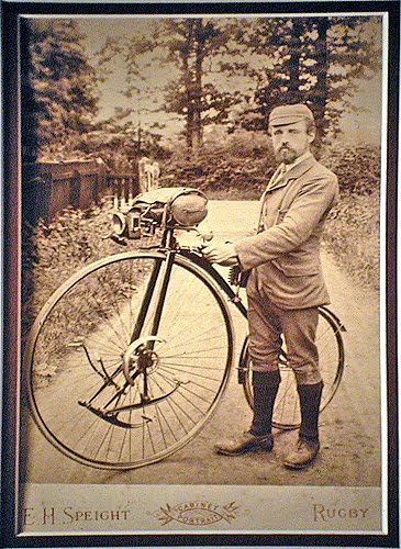
This page is from the 1884 Ellis & Co. catalog from my own collection.
Email me, using the link at the right, if you'd like a complete scanned copy.
Ellis and Co. have used at least two styles of con rods on the geared faciles. Early ones such as the Percy Nix machine in the Coventry museum has tubular arms, later ones are solid and much more slender in section. I'm going to be making the later style.
The Percy Nix machine from 1888 (second year of production) has the earlier, tubular style of con rods.
The later style are solid and much more slender.
You can see from the photo above that three of the ends are identical (apart from oiler placement) which means I can make all three at the same time. If I had access to a big lathe, I'd simply make each con rod from a single piece of stock and bore each end at a time. The centres on the con rods are 8.5" and I would need a fairly hefty lathe to swing that, even in the gap. I don't have access to such a machine so I'll do it in sections on my trusty little Myford and then join them up. The right hand con rod will be made in three sections, both the ends and a centre section. The left hand con rod will be made in two parts since the top end doesn't need to be turned. I'm having a dilemma about how to successfully join the sections. I could ask Pete the Welding Ninja to TIG them up for me or I could silver solder them with a lap joint. The difficulty comes from the need to harden the bearing surfaces. I'm going to have to think about this. As usual, here's a stack of photos.

Calculate the minimum size of bar stock required and mill a flat on each side.
Then saw it into the three pieces and mark out the shape of the end.
I'm going to bore the holes and bearing surfaces in a four jaw so I need to remove as much material as possible from the stub to prevent vibration when running off centre at speed.
Mill the sides so that the stub is at the correct width.
Roughly file the fillet from the stub to the body and mill the corners off
so that the shape can be held securely in the four jaw.
Repeat with the front and back.
I've left enough material to produce a nice fillet between the end and the shaft.
I've needed to make a parallel spacer out of some scrap tube
to ensure that the work sits square in the four jaw
Centre on the marked punch and drill and bore the central hole
Also clean up the outer face. I can't profile the outer edge at this time as I need
the flat surface to align square against the parallel spacer when it's turned around.
Rough out the shape of the bearing surface at a 45 degree angle...
...and use the profile tool to machine the bearing. Then polish the surface.
Then flip over, re-centre on the bore and repeat.
Next mount on a mandrel...
...and machine the edge profiles.
Then mount on the mill and clean off all the 'corners'. I would like to use a rotary table
for this but I haven't got one so I use my dividing head instead.
Finally give them a little tickle with a file. I'll wait until I have the centre section made
before I profile the stub that attaches to it. As I said I need to have a think about it first.
In other news, I did a most stupid thing this weekend. When Pete (hired muscle) came and Kung Fu'd up the old deck, we just threw the wood into a heap behind the facile factory. I'd been meaning to do something about it ever since but my lovely wife forced my hand this weekend and made me do it. The old deck boards had many rusty old nails sticking out at all sorts of dangerous angles. I laid the boards down and knocked the nails flat with a hammer before sawing the timber up for our wood burner this winter. The timber is untreated hardwood so useful as fuel. I thought I'd got all the nails done and went inside briefly to answer the phone. Afterwards I ran down the back door steps and put my full body weight on the one remaining nail that I'd missed. It pierced the sole of my shoe and then carried on through my foot and came out the top. Of course the nail was a special deck nail with annular grooves that made it hard to get out. I had to put my other foot on the board and yank my crucified foot off the nail. Being male, I naturally didn't go to the doctor until it had got properly infected and had gone an interesting colour. I thought I'd had a tetanus when I had my spectacular crash two years ago but apparently not, my last recorded one being in 1993. Probably best that I don't put a photo of my foot up I think. It does mean that I'm having to soft pedal with my right foot and standing on the pedals is out of the question.

An annular grooved nail, yesterday.