I wonder where the birdies is?
etc.
In stark contrast to last week, Spring appears to have been switched on at last. The birdies in the above poem (incidentally not by Spike Milligan as I always thought) being magpies. We are nearly in the attack season again, I know this because I had one shout at me last weekend, next weekend he will be dive bombing me. But I digress.
This week I have made the top lock nut for the ball head, I have chosen to make the flush variant as I won't be using a lamp bracket mounted on the head. The original I am copying does have a lamp bracket as did the Percy Nix machine in the Coventry museum. This machine was used for the 24 hour race and would certainly have required a lamp for the night time part of the event.

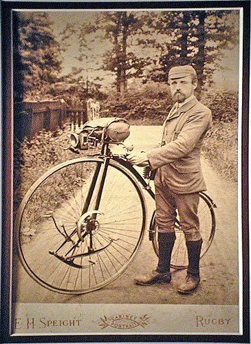
This is a photo of the bike taken in or prior to 1931 (when it was in the Sammy Bartleet collection)
and the lamp bracket is clearly visible. From Bartleet's Bicycle Book, 1931

The bracket has now disappeared as in this photograph I took just a few months ago of the same machine.

But this is what the flush variant looks like, neat eh?
The Upper example is an early geared facile and the lower is a non geared model, both by Ellis & Co.

Machining the lock nut just involved simple turning and screw cutting
plus a little indexing to get the holes in the correct place.
Now I can mount the completed neck into the head itself and establish
a) the length of the backbone to provide the correct inclination of the forks, this effects the trail of the machine and consequently how it handles.
b) the correct angle of the backbone to maintain an even gap between the wheel and the backbone. Although saying this, I have seen backbones on originals all over the place, some are very closely fitted with an even gap and some are not. Of the various originals I have now seen and measured, I have yet to see two the same, a remark echoed by other collectors that own these machines.
The angle of the forks likewise seems to vary hugely, the very early machines are more upright, something that is clear in the advertisements and literature. I've measured several from 1887 that have as little as 5 degrees inclination on the forks. This is in contrast with younger bikes that have up to 16 degrees inclination. The anomaly here is the racer from 1888 that has a full 20 degrees, this would produce a high trail value (for the period) that would be more stable at higher speeds with more rider fatigue. This is just my theory at present, I suspect it could probably be able to be ridden hands off.
As an aside I am currently reading the excellent new book on Dan Albone and Ivel cycles by Ray Miller and Lee Irvine (ISBN 978-0-9566337-4-3 available from the VCC UK). In chapter 5 Ray discusses how in 1886, Albone invented the first rear driving safety that could be ridden hands off, the discussion mentions the steering geometry being responsible but no actual mention of the trail. A friend of mine owns an 1887 Ivel safety locally (it is photographed in the book). Next time I see it, I'll measure the trail and report back. Clearly, steering geometry was beginning to be understood a little more by this time and I see no reason why Ellis & Co. wouldn't have adopted the current thinking at the time to slacken the head angle to provide more trail. I have decided to use an inclination of 16 degrees (the same as the original I am copying) which will give a moderate amount of trail.
The next job is to file the stub on the neck casting to be a very accurate fit into the backbone. I have made a little jig from part of the off cut backbone, this jig is coated with engineers blue, an evil substance that will coat everything within a 100 metre radius if children and cats are allowed into the workshop at the same time as the tube is open. The idea is that the backbone is placed into the jig and the high spots are marked by the blue, these high spots are then filed off and the process repeated. Great care being taken not to twist the casting relative to the jig. This took many hours, but the care has paid off and I now have a very well fitting backbone that should braze easily.

The jig to mark the high spots on the casting,
shortly before engineers blue covered everything.

File off the marked high spots and repeat. Carefully.

Eventually, an accurate fit is obtained.

The backbone can now be cut to length.

A little trigonometry to ensure the forks are inclined at the correct angle before any cutting takes place.
Ensure that both wheels are on a horizontal surface and the above chart is taped vertically
to the wall behind the bike, then simply line up the forks with the chosen angle by line of sight.
Measure twice, cut once.

The tube has been left slightly proud of the edge to assist in the brazing process.
It will be filed flush afterwards.
The final job is to hollow out the stubs for all the reasons previously stated.

At last we can now do a dry assembly to see how it all fits together.

Still to do on the backbone is to make the step which is a simple folded piece of steel brazed to the left fork leg. I also need to drill and tap the holes in the rear fork crown to allow a mudguard to be mounted.
In other news, I have promised my lovely wife that I will build her a new deck when spring arrives. I fear that my shed fettling will have to take a back seat for a period if this good weather continues. I did try to bribe my brother to come and build it but he pretended not to hear me.
No comments:
Post a Comment